
Can a Gyroscope Be Used as an Attitude Sensor?
Integrating MPU6050 gyro rates into roll, pitch and yaw. It passes straight through the orientation where the accelerometer breaks down, it is the only source of relative yaw, and over five stationary minutes it wandered 1.1, 0.8 and 0.37 degrees. Then the temperature moved.
Published
In the previous experiment we looked at a fundamental limitation of using an accelerometer to estimate inclination.
An accelerometer can use gravity as a reference, but that reference becomes problematic at certain orientations. Around 90° of inclination a small measurement error can produce a surprisingly large error in the calculated angle.
So what happens if we use a gyroscope instead?
A gyroscope does not measure inclination directly. It measures angular velocity. By integrating that angular velocity over time we can obtain a relative change in orientation.
This sounds promising. But integration introduces another problem: drift.
This experiment investigates both sides of that trade. The acquisition configuration is unchanged from the previous experiments — 1 kHz sampling, internal low-pass filter at about 21 Hz, ±2 g and ±250 °/s ranges. EmbedStudio read the firmware’s own attitude variables over SWD at roughly 275 samples per second.
From Angular Velocity to Angle
The MPU6050 gyroscope measures angular velocity, expressed in degrees per second.
If the sensor rotates at 20 °/s for one second, its orientation changes by approximately 20°.
In general the angle is obtained by integrating angular velocity:
For discrete measurements this becomes:
where is the current angle, is the measured angular velocity and is the time between samples.
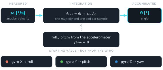 Figure 1 — The whole estimator. One multiply and one add per axis per sample, plus a starting value the gyroscope itself cannot supply. The three axes are accumulated independently, which is a simplification discussed below.
The firmware implementation is deliberately simple:
// Resets the orientation angles in gyro_angles to the value provided by gyro_init
void ahrs_gyro_reset(vector_3f_t* const gyro_angles, const vector_3f_t* const gyro_init)
{
	memcpy(gyro_angles, gyro_init, sizeof(vector_3f_t));
}

// Updates the orientation angles by integrating the angular velocities for each axis
// This implementation is not correct and is build for demonstration of how the gyro works
void ahrs_gyro_loop(const vector_3f_t* const gyro, const float dt_s,
		vector_3f_t* const angles)
{
	for (uint8_t i = 0; i < VECTOR_3F_N_ELEMENTS; ++i) {
		angles->v[i] += gyro->v[i] * dt_s;
	}
}
ahrs_gyro_reset() initializes the accumulated angles. ahrs_gyro_loop()
integrates every new gyro sample. The dt_s it receives is the measured
interval from experiment #004,
not a nominal one.
The three gyro axes are integrated independently. The comment in the source says what that is: a demonstration, not a correct attitude filter.
In a general 3D attitude estimator, body-frame angular velocity and Euler-angle rates are not the same thing. The exact relationship depends on the current orientation and couples the axes. That mathematics is useful when building a complete estimator. It is not needed to answer the question this experiment asks, and the simplification keeps the focus on how the gyroscope itself behaves. The recording in the roll section shows exactly where it stops being adequate.
How Do We Initialize the Gyroscope?
There is one immediate problem.
The gyroscope measures rotation, but it does not know where the sensor started.
If the sensor is lying at 30° when the system starts, integrating the gyro cannot tell us that the initial angle was 30°. It only tells us how much the orientation has changed since then.
An initial orientation therefore has to be provided from somewhere else.
For roll and pitch we can use the accelerometer, because gravity provides a reference for the vertical direction. Yaw is different. Gravity carries no information about rotation around the vertical axis, so yaw cannot be initialized to an absolute heading from the accelerometer.
The initial values are therefore:
There is one more detail in the firmware. After power-up the gyro zero-offset estimator needs time to determine the sensor bias, and it only banks samples while the board is genuinely still. Until that estimate is ready the gyro angles are reset on every iteration:
if ((!gyro_inited && (mpu_data.sample_count > N_SAMPLES_BEFORE_GYRO_INIT))
|| !gyro_zero.ready
|| gyro_init_request) {
	gyro_inited = 1;
	gyro_init_request = 0;
	vector_3f_t init_angle = {
			.x = attitude_deg.roll,
			.y = attitude_deg.pitch,
			.z = 0,
	};
	ahrs_gyro_reset(&gyro_angles_deg, &init_angle);
}

ahrs_gyro_loop(&gyro_dps, (mpu_data.sample_time_us) / US_IN_S, &gyro_angles_deg);
Once the zero-offset estimate is ready the automatic resetting stops, and the
angles are updated by integration alone. The gyro_init_request flag can still
force a reset. That flag is an ordinary firmware variable, so during these
experiments the integration was restarted by writing to it from EmbedStudio,
without rebuilding anything.
That boundary is visible in the recording.
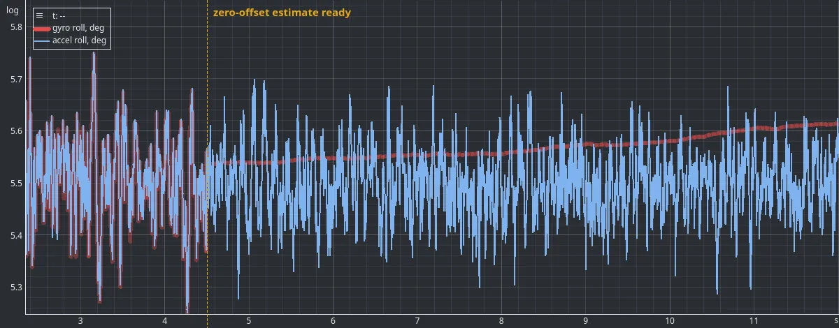 Figure 2 — The moment the integrator is let go. Left of the line the gyro angle is reset to the accelerometer angle every iteration, so it carries the accelerometer’s noise exactly; the two traces never differ by more than 0.04°. Right of it, the same channel is smooth and moves 0.16° in twelve seconds, while the accelerometer keeps wandering over a 0.43° band.
That one figure already contains the whole trade. The integrated angle is far smoother than the accelerometer estimate, and it is slowly going somewhere.
The processing chain is therefore:
gyro zero-offset estimation → initial attitude → gyro integration → accumulated roll, pitch and yaw
Pitching Through 90 Degrees
The first experiment revisits the problem measured in experiment #007.
The sensor was rotated in pitch, past 90° and back.
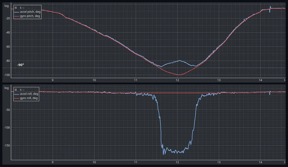 Figure 3 — One sweep past vertical. Top: pitch. The accelerometer estimate (blue) reaches −88.9° and folds back towards zero; the integrated one (red) continues to −100.0° and returns. Bottom: roll, on the same time axis. The accelerometer roll swings to −176.4°; the integrated roll stays inside a 0.55° band the whole time.
Two different things happen to the accelerometer estimate here, and they are worth separating.
The first is the one measured in experiment #007. As pitch approaches −90° the projection of gravity that the roll formula depends on shrinks into the noise, and the calculated roll starts moving even though the board is not rolling.
The second is not an error at all. Past vertical, the same orientation is described by moving roll to about 180° and bringing pitch back towards zero. Both estimates are correct, and the accelerometer has no way to choose between them. So its pitch turns around at the boundary and its roll jumps almost half a revolution.
The gyroscope has neither problem. It measured the rotation as it happened and accumulated it, so the pitch it reports is one continuous number that passes through −90° without noticing it. Over the same two seconds, while the accelerometer roll was moving over most of its range, the integrated roll moved by 0.55°.
This is the important difference between the two sensors:
the gyroscope does not need gravity to determine the change in orientation.
It measures the rotation itself.
Rolling Through 90 Degrees
The same experiment was repeated around the other inclination axis. The board was rolled past 90° and returned.
The result is different, and it is worth stating plainly: the accelerometer
is fine here. Rolling through 90° is not a singular orientation for the roll
equation. Roll is atan2(ay, az), and at 90° of roll the Y component is at a
full g, which is as well conditioned as this calculation ever gets. The
singularity in experiment #007 belongs to pitch approaching ±90°, not to
inclination in general.
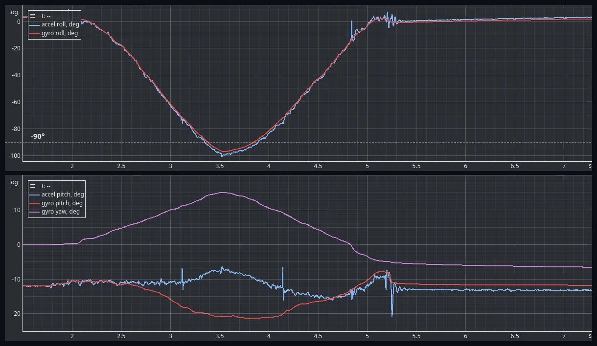 Figure 4 — Rolling past vertical. Top: the two roll estimates agree through −100°, to a median of 1.0° and to 2.5° at the ninetieth percentile. Bottom: the price of integrating the three axes independently. Gyro pitch (red) leaves the accelerometer pitch (blue) by up to 10° during the rotation and returns to within 0.15° of where it started, and gyro yaw (purple) does the same.
So the top panel says what this article is about: over a fast, large, hand-held rotation the integrated angle tracked the accelerometer estimate to about a degree. The differences that remain are mostly the accelerometer’s, not the gyro’s. The board is being turned by hand, so the accelerometer is measuring gravity plus the hand, and the magnitude of the measured vector reaches 1.28 g during the sweep. That is the failure mode measured in experiment #006, and it is exactly what a gyroscope is immune to.
The bottom panel is where the simplification shows. Gyro pitch started at −11.9°, moved to −21.4° during the roll, and came back to −11.8°. Gyro yaw did the same, out to +15.1° and back. The accelerometer pitch stayed between −16.1° and −6.4° throughout, so the board’s pitch did not really change by twelve degrees.
The excursion appears during the rotation and disappears when it stops. That is the signature of axis coupling, not of drift. With the board rolled onto its side, a rotation the operator makes about one axis is partly seen by the gyroscope on another, and three independent accumulators have no way to sort that out. A proper attitude estimator does. This one is not one, and the figure is the measurement of how much that costs.
A Capability the Accelerometer Does Not Have: Yaw
The accelerometer can determine the direction of gravity, which gives roll and pitch. But rotating the sensor around the gravity vector does not change the direction of gravity.
An accelerometer alone therefore cannot determine yaw. A gyroscope can.
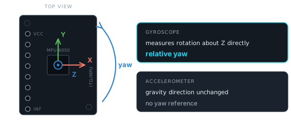 Figure 5 — Yaw is rotation about the sensor Z axis. Held level, that axis points along gravity, so the accelerometer reads the same three numbers before and after the turn. The gyro Z channel reads the rotation rate directly.
For the yaw experiment the board was turned about its vertical axis while staying approximately level. It was moved by hand in four steps of roughly a quarter turn each.
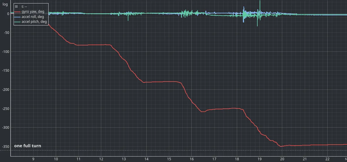 Figure 6 — A full turn about the vertical axis. The integrated yaw (red) follows every step and settles at −346°. The accelerometer’s roll and pitch (blue and green) stay inside ±5° and ±8° for 98% of the rotation, apart from isolated single-sample excursions. There is nothing in them to read a heading from.
The four plateaus sit at −82.5°, −179.7°, −251.3° and −346.3°. Those are where the operator’s hand stopped, not calibration points: the board was turned without a jig and there is no external heading reference in this recording to check the total against. What the figure shows is that the rotation was followed at all, by a sensor pair in which one half is completely blind to it.
Of course this does not mean that the gyro knows the absolute heading. If we initialize yaw to zero, the gyro can tell us that the sensor subsequently rotated by, for example, +40° or −90° relative to that initial orientation.
It cannot tell us that the sensor is pointing north.
So the distinction is:
gyro → relative yaw
magnetometer or another external reference → absolute heading
How Stable Is a Gyro When Nothing Is Moving?
The main weakness of gyro integration is drift.
Even when the sensor is completely stationary, the measured angular velocity is not exactly zero. Suppose the real angular velocity is zero but the gyro reports a constant error of 0.1 °/s. After one second the accumulated error is 0.1°. After one minute it is 6°.
This is the fundamental problem with integration: a small bias becomes an angle error that grows with time.
How large is that effect in practice for the MPU6050?
The sensor was initialized and then left alone for five minutes. The die temperature moved by 0.14 °C over the whole recording, so conditions were about as steady as a desk gets.
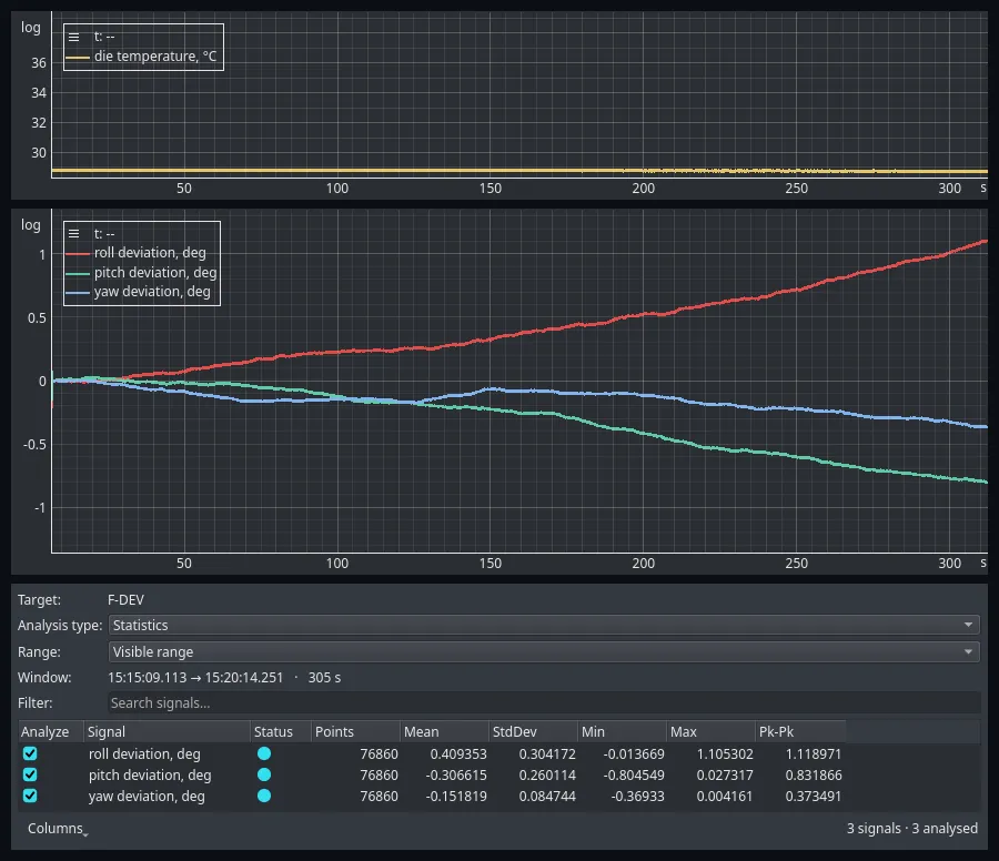 Figure 7 — Five stationary minutes, measured by the Analysis panel. Top: the die temperature, on the same scale as figure 8, where it is a flat line. Middle: each integrated angle minus the attitude the integrator was started at, so zero is the initial attitude. Over 305 s and 76 860 samples the extremes are +1.11° in roll, −0.80° in pitch and −0.37° in yaw. Note the angle scale — figure 8 uses one seventeen times wider.
| Axis | Maximum deviation | Implied residual bias |
|---|---|---|
| Roll | 1.11° | 0.0036 °/s |
| Pitch | 0.80° | 0.0026 °/s |
| Yaw | 0.37° | 0.0011 °/s |
Table 1 — Deviation from the initial attitude over 305 stationary seconds, and the constant rate that would produce it. The die temperature stayed within 0.14 °C.
These results are surprisingly good for a low-cost MEMS gyroscope. Over five minutes the integrated orientation stayed within about a degree on roll and pitch, and the yaw deviation was smaller still.
Two things put that in context.
The drift is not random walk here, it is a slope. Each trace moves in one direction at a nearly constant rate, which is what a small residual bias looks like. Dividing the deviation by the window gives biases of a few thousandths of a degree per second, thirty to ninety times smaller than the 0.1 °/s used as an illustration above.
And the accelerometer estimate, over the same five minutes on the same stationary board, wandered over 0.49° in roll and 0.51° in pitch without going anywhere. For the first minute or two of this recording, the noisier of the two estimates is the one that cannot drift.
None of this eliminates gyro drift. It shows that for short-term applications, gyro integration can be considerably more useful than the word “drift” might suggest.
What Happens When the Temperature Changes?
The previous result was obtained under steady temperature. That matters, because the gyro bias is not necessarily constant.
A stationary sensor can therefore show a changing integrated angle even though its physical orientation has not moved. One practical source of that behaviour is temperature.
A second stationary recording was made while the sensor temperature was allowed to change. The board had been handled, so it started warm at 38.5 °C, and it was left to cool.
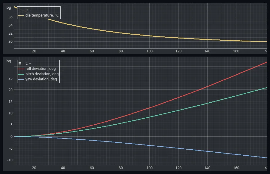 Figure 8 — The same measurement, with the temperature moving. Top: the die cools from 38.5 °C to 29.9 °C, on the same scale as figure 7. Bottom: the integrated attitude of a board that never moved, running away by 31.8°, 20.9° and −9.1° — the angle scale spans 46° here against 2.7° in figure 7. Temperature dependence is demonstrated qualitatively; a controlled thermal characterization is a separate experiment.
The board was as stationary as in the previous recording — its accelerometer roll and pitch stayed inside 0.8° and 0.5° bands throughout. The integrated attitude nevertheless left by more than thirty degrees.
Averaged over that window the roll drift rate was 0.18 °/s, against 0.0036 °/s with the temperature steady. A milder version of the same recording, over a 0.6 °C fall rather than an 8.6 °C one, gave 4.6° of roll in three minutes. Both are in the dataset.
Two measured rates on the same board are not a temperature coefficient, and nothing here should be read as one. The recording is not controlled: the cooling rate, the starting temperature and the gradient across the package were all whatever they happened to be. Characterizing the coefficient needs a controlled temperature range and is planned as its own experiment.
What the recording does establish is the practical fact:
gyro bias changes with operating conditions, so a zero-offset estimate taken at startup does not stay valid indefinitely.
What Have We Learned?
The experiments show that a gyroscope is a capable short-term attitude sensor.
What the gyroscope does well
It measures rotation directly. The gyro does not infer rotation from gravity, so it tracked the board smoothly through the orientation where the accelerometer estimate breaks down, and past it.
It provides relative yaw. Unlike the accelerometer, the gyro can detect rotation around the gravity vector. It followed a full revolution that the accelerometer could not see at all.
It is immune to linear acceleration. During the hand-held sweeps the measured acceleration reached 1.28 g and the accelerometer attitude moved with it. The gyro did not.
Its short-term estimate is smooth and steady. In the five-minute stationary recording the deviations from the initial attitude were 1.11° in roll, 0.80° in pitch and 0.37° in yaw.
What the gyroscope cannot do
It cannot determine the initial orientation by itself. An initial attitude has to come from another sensor or another system.
It cannot provide absolute heading. A gyro measures changes in yaw. Without an external heading reference it does not know the absolute direction.
It drifts. Even a small measurement bias accumulates through integration, and the error grows for as long as the integration runs.
Its bias changes. Cooling by 8.6 °C turned a 0.0036 °/s residual bias into an average of 0.18 °/s, and thirty-two degrees of roll error in three minutes.
Three independent accumulators are not an attitude estimator. Rolling the board onto its side moved the integrated pitch by twelve degrees and put it back afterwards. That is coupling between the axes, and it is a property of the simplified model rather than of the sensor.
Conclusion
The gyroscope provides a fundamentally different way of estimating attitude.
Instead of using gravity as an absolute reference, it measures angular velocity and integrates it over time. That makes it good at tracking short-term rotational motion, and it avoids the geometric limitation measured around 90° in the previous experiment. It also provides something the accelerometer cannot: relative yaw.
But the price is drift.
The gyro does not know where it started, and every small bias in its measurement accumulates into the estimated angle. Under steady conditions the MPU6050 held a surprisingly good short-term attitude estimate. Let the temperature move by a few degrees and the same board wandered by thirty.
So we now have two sensors with complementary strengths.
The accelerometer provides an absolute reference from gravity, but its estimate is disturbed by motion and becomes unusable at certain orientations. The gyroscope handles rotational motion well, but its estimate inevitably drifts because it has no long-term reference.
Perhaps the best solution is not to choose one sensor over the other, but to use both.
That is what we will investigate next.
Experiment data
The raw datasets used in this experiment are publicly available in the EmbedStudio Experiments repository.
The dataset contains:
- the gyro initialization capture, in which the integrator is released the moment the zero-offset estimate becomes ready;
- the pitch sweep past vertical and the roll sweep past vertical;
- the yaw rotation through a full turn;
- the five-minute stationary recording used for the drift measurement, and a three-minute one at the same steady temperature;
- two stationary recordings with the temperature moving, one over 8.6 °C and one over 0.6 °C.
Every capture carries the three calibrated accelerometer channels, the three calibrated gyro rates, the accelerometer attitude, the three integrated gyro angles, the zero-offset estimator state and the die temperature.
The EmbedStudio workspace the captures were recorded with is in the repository as well. It carries an extra Article figures dashboard whose views are the ones the screenshots above were taken from, so opening a capture with it puts the same plots on the screen.
All datasets are provided as HDF5 files and can be downloaded and opened with EmbedStudio or another compatible HDF5 tool.
Frequently Asked Questions
How do you calculate an angle from a gyroscope?
By integration. Each sample of angular velocity is multiplied by the time since the previous sample and added to a running total, so theta at step k plus one equals theta at step k plus omega at step k times delta t. On the MPU6050 that is one multiply and one add per axis per sample. The gyroscope measures how fast the sensor is turning, not where it is pointing, so the running total is a change in orientation rather than an orientation.
Can a gyroscope alone measure inclination?
Only relative to wherever it was started. Integration gives the change in orientation since the accumulator was initialized, so an initial attitude has to come from somewhere else. In this experiment roll and pitch start from the accelerometer, which can see the direction of gravity, and yaw starts at zero because gravity carries no heading information.
Does the gyroscope have the same 90 degree problem as the accelerometer?
No. In the recording here the board was tipped past vertical. The accelerometer pitch stopped at minus 88.9 degrees and folded back towards zero while its roll jumped to minus 176 degrees, which is a correct but discontinuous description of the same orientation. The integrated gyro pitch went straight through to minus 100 degrees as one continuous number, and the integrated roll stayed inside a 0.55 degree band while the accelerometer roll swung across most of its range.
Why can a gyroscope measure yaw when an accelerometer cannot?
Because it measures rotation itself rather than the direction of gravity. Turning the sensor about the vertical axis leaves the gravity vector unchanged, so the accelerometer reads the same three numbers throughout. The gyro Z axis reads the rotation rate directly. In the recording here the board was turned by hand through a full revolution and the integrated yaw accumulated minus 346 degrees while the accelerometer roll and pitch stayed inside a few degrees of level.
Does a gyroscope give absolute heading?
No. It gives a change of heading relative to whatever the accumulator was started at. If yaw is initialized to zero, the gyro can say the sensor has since turned by plus 40 or minus 90 degrees, but it cannot say the sensor is pointing north. Absolute heading needs an external reference such as a magnetometer.
How much does an MPU6050 gyroscope drift when it is not moving?
On this module, left stationary for five minutes with the die temperature steady within 0.14 degrees Celsius, the integrated attitude moved 1.11 degrees in roll, 0.80 degrees in pitch and 0.37 degrees in yaw away from the attitude it started at. Those correspond to residual biases of about 0.0036, 0.0026 and 0.0011 degrees per second. That is a lot better than the word drift usually suggests, and it is still an error that grows for as long as the integration runs.
Does gyro bias change with temperature?
Yes, and enough to dominate everything else. A second stationary recording started with the sensor at 38.5 degrees Celsius and let it cool to 29.9 over about three minutes. The integrated roll ran away by 31.8 degrees, an average rate of 0.18 degrees per second against 0.0036 with the temperature steady. A zero-offset estimate is only valid for the conditions it was measured in, and this recording is a qualitative demonstration rather than a characterization of the temperature coefficient.
Why does integrating the three gyro axes independently not give correct Euler angles?
Because body-frame angular rates and Euler-angle rates are only the same thing near level. The exact relationship depends on the current orientation and couples the axes. In the roll recording here the board was rolled past 90 degrees and the integrated pitch moved from minus 11.9 to minus 21.4 degrees and back to minus 11.8 while the accelerometer pitch stayed between minus 16 and minus 6. The excursion appeared during the rotation and disappeared afterwards, which is what coupling looks like rather than drift.
Source Code
The firmware and supporting files for this experiment are available here:
View experiment repository