
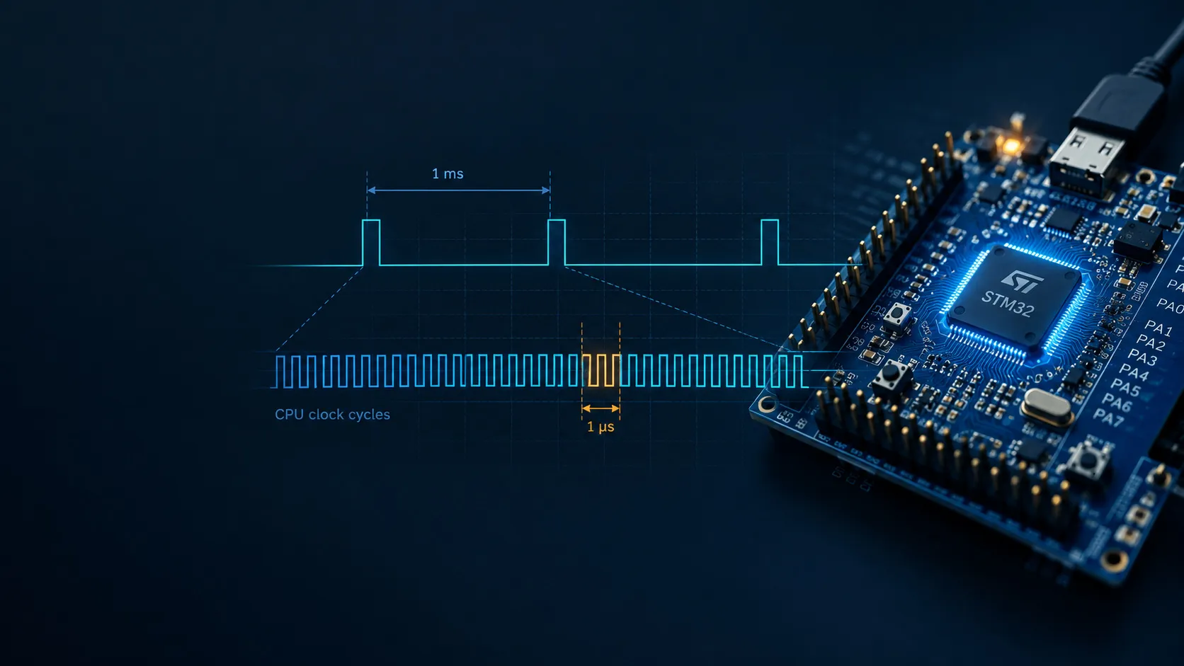
Measuring Time on an MCU — Why the HAL Tick Is Not Enough
Learn how to measure MCU execution time using the ARM Cortex-M DWT cycle counter, why a 1 ms HAL tick is too coarse for short measurements, and how to handle counter wraparound.
Published
Have you ever measured how long a function takes on an STM32 and got zero milliseconds?
That doesn’t necessarily mean the function is fast. It may simply mean that your timer is too coarse for the job.
The HAL tick is convenient for delays and timeouts, but when investigating sensor sampling, filtering or control loops, we often need to measure time on a much smaller scale.
Let’s look at a simple alternative: the cycle counter available in the Data Watchpoint and Trace (DWT) unit on supported ARM Cortex-M processors.
1. The problem with milliseconds
A typical STM32 project uses HAL_GetTick() to read a millisecond counter.
uint32_t start = HAL_GetTick();

do_work();

uint32_t elapsed_ms = HAL_GetTick() - start;
This is perfectly fine for measuring how long a communication timeout has lasted or whether a delay has expired.
But what if do_work() takes 20 microseconds?
A counter that advances once per millisecond cannot reliably measure that duration. Depending on where the operation falls relative to a tick update, the result might be zero or one millisecond.
Increasing the tick frequency is possible in some systems, but it introduces more frequent interrupts and still isn’t the most convenient way to measure short execution times.
The solution is to measure processor cycles instead of milliseconds.
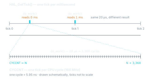 Figure 1 — The same 20 µs operation on both timelines. The 1 ms tick reports 0 or 1 ms depending on where the operation falls; the cycle counter records 3,360 cycles. A schematic, not a measurement: the cycle ticks are not drawn to scale.
2. Meet the DWT cycle counter
Many ARM Cortex-M processors provide a hardware counter called CYCCNT, part of the Data Watchpoint and Trace (DWT) unit.
Once enabled, this counter increments with processor clock cycles. We can read it before and after an operation and calculate the difference.
At a core clock of 168 MHz, one cycle lasts approximately 5.95 nanoseconds. An operation taking 20 microseconds would consume roughly 3,360 cycles.
That gives us a much finer timing resolution than a millisecond tick.
The DWT is a processor debugging and profiling facility with features beyond cycle counting. For more details, see Arm’s CMSIS documentation for the DWT registers. For a deeper explanation, consult the technical reference manual for your specific Cortex-M processor. Arm’s Cortex-M33 Technical Reference Manual is one example.
One caveat: not every Cortex-M implements the cycle counter. Cortex-M0 and M0+ do not provide this DWT cycle counter, and support should be checked for the specific processor.
3. Measuring elapsed cycles
The basic technique is simple:
uint32_t start = read_cycle_counter();

do_work();

uint32_t elapsed = read_cycle_counter() - start;
The counter is free-running, so we don’t need to reset it for every measurement. We just take two readings and subtract them.
There is also a useful detail in C: unsigned 32-bit subtraction naturally handles counter wraparound. As long as the measured interval is shorter than the full counter period, the elapsed cycle count remains correct even if the counter rolls over between readings.
At 168 MHz, a 32-bit cycle counter wraps approximately every 25.6 seconds. For measuring individual functions or sampling intervals, this is generally not a concern.
Of course, the measurement itself has some overhead. Interrupts can also contribute to the measured duration. Those effects matter when interpreting the result, especially for very short operations.
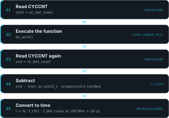 Figure 2 — The measurement sequence: two readings of CYCCNT around the function, one unsigned subtraction, one division by the core clock.
4. Turning cycles into time
Cycle counts are useful, but microseconds are often easier to reason about.
The conversion is straightforward:
where is the measured cycle count and is the core clock frequency.
For example, 3,360 cycles at 168 MHz correspond to 20 microseconds.
The important detail is to use the actual core clock frequency. If the clock configuration changes, the conversion must be updated too.
For routine measurements, floating-point conversion is convenient. When a rounded integer result is needed, integer conversion is another option. Neither approach makes the measurement infinitely precise: the quality of the result still depends on the hardware, the measurement method and the conversion precision.
5. From a single measurement to a sampling interval
In an IMU application, measuring the execution time of a function is only part of the story.
We may also want to know the actual interval between successive samples. A filter might be designed around a nominal 1 ms period, but the firmware needs to use the interval it actually experiences if timing variation is relevant to its calculations.
A simple interval helper can retain the previous timestamp and calculate the difference at every update. This avoids resetting the hardware counter and makes repeated measurements straightforward.
The placement of the timestamp matters, though. Measuring between two calls in the main loop tells us the interval between those calls—not necessarily the exact interval between physical sensor conversions. If the latter matters, the sensor’s data-ready signal or a hardware timer capture may be more appropriate.
The MPU-6050 series has a worked example of exactly this: MPU6050 Timing and Sampling reads the cycle counter inside the data-ready interrupt and measures the sensor’s real sampling interval.
6. A small reusable implementation
Across embedded systems projects, I often find myself implementing the same kinds of utilities: timing measurements, filtering, statistics and other building blocks that are useful regardless of the application.
EmbedTools is my effort to collect these utilities into a small, reusable C library, growing incrementally from practical engineering work rather than from a predefined framework.
The DWT-based timing module is one of its first building blocks. It separates portable cycle arithmetic and time conversion from Cortex-M-specific hardware access, without depending on STM32 HAL. This makes the core functionality reusable across projects while keeping the hardware-specific parts explicit.
Using the timing module looks like this:
et_dwt_init(cpu_hz);

uint32_t start = et_dwt_now();

do_work();

uint32_t cycles = et_dwt_elapsed(start);
float elapsed_us = et_dwt_to_us(cycles);
For a real project using it, see the MPU-6050 firmware, which includes EmbedTools as a Git submodule in libs/EmbedTools.
The goal is straightforward: when a useful piece of embedded code proves itself in one project, it should be possible to reuse it in the next without copying and maintaining another implementation.
The library will evolve as new needs emerge from real projects. This timing example is one such utility—not a claim that every embedded system needs another abstraction layer.
7. What can we do with it?
Once we can measure time at a useful resolution, we can start answering practical questions:
-
How much execution time does a filtering algorithm consume?
-
Does the sampling interval remain stable?
-
How much do interrupt handling and other background activity affect timing?
-
Does a firmware change improve performance, or just make the code look simpler?
Measurements are most useful when we can observe them over time and compare them with other runtime variables. For example, looking at sensor data alongside sampling intervals can help distinguish an algorithmic problem from a timing problem.
For this kind of investigation, a firmware-variable inspection tool such as EmbedStudio can complement cycle-counter measurements by making runtime variables easier to inspect without adding logging statements throughout the firmware.
The general lesson is simple: don’t rely only on the timing you intended to implement. Measure what the running firmware actually does.
Final thoughts
The HAL tick remains a good tool for millisecond-scale timekeeping. It just isn’t designed to measure every short operation inside a real-time loop.
On a supported Cortex-M processor, the DWT cycle counter provides a straightforward alternative. A couple of timestamps, unsigned subtraction and a known clock frequency are enough to get started.
Sometimes, understanding a real-time system begins with a very small change: measuring time at the right scale.