
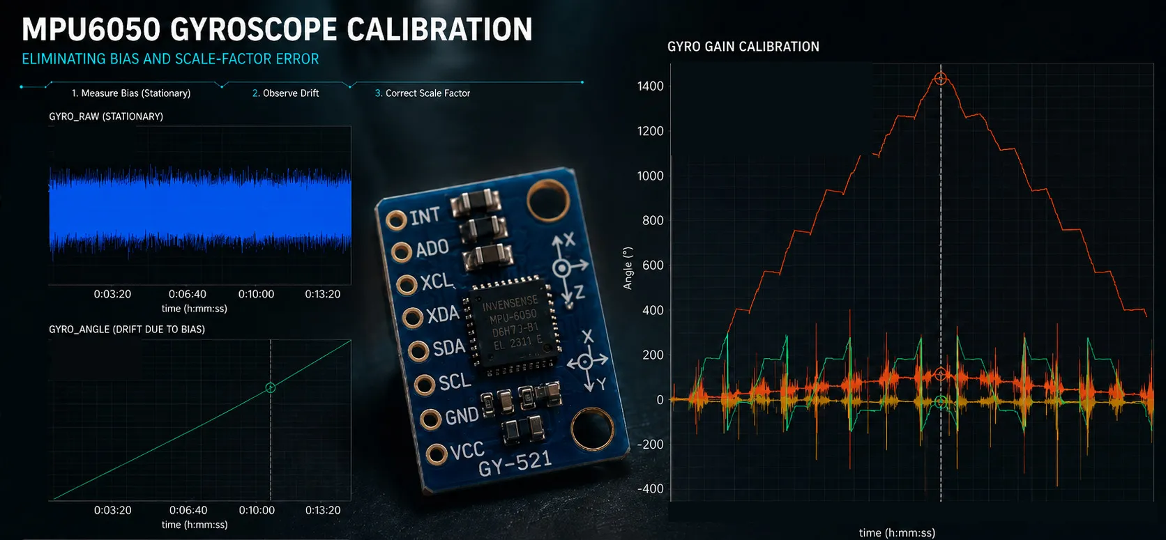
MPU6050 Gyroscope Calibration: Bias Compensation and Scale Factor Without a Rate Table
How to calibrate an MPU6050 gyroscope with nothing but gravity and a pair of hands — measuring the zero point at startup, extracting the scale factor by tilting between two resting positions, and comparing what each compensation actually buys.
Published
An accelerometer has it easy. Gravity is 1 g, it is there whenever the device is still, and any reading that disagrees is the sensor’s fault. That is what made the previous experiment possible with nothing but a pair of hands.
A gyroscope has no such luxury. It measures a rate, and nothing in the room is rotating at a known one. You get one free reference: at rest, the true rate is zero. That fixes the zero point. It says nothing at all about the scale factor.
This experiment is about the way around that. You do not need a known rate. You need a known angle, because integrating rate gives angle. And the previous experiment left behind something that measures angles to a fraction of a degree, using gravity as its reference.
The accelerometer calibration becomes the gyroscope’s rate table.
What this experiment found
- A gyroscope’s zero point moves every time you power up. On this part, warm and untouched, it shifted by 0.043 °/s between power-ups — enough to accumulate 2.6° of heading error after one minute of sitting perfectly still.
- Zero the gyro at startup, don’t compile a stored constant into the firmware. Average two seconds of output while the board is still, then subtract it. After one minute that leaves 0.065° of error against 4.6° — more than 70× better.
- The scale factor does not move, and you can measure it without a rate table. Tilt the board between two resting positions, let the accelerometer measure the angle, integrate the gyro across the move, divide. One axis of three came out 0.9 % above the datasheet’s 131 LSB/(°/s) while the other two sat within 0.1 % of it.
- Scale is a property of the part. Bias is a property of the moment. Compile the scale factor in. Measure the zero point at every startup.
- Turn the board too fast and the measurement breaks without saying so. A 180° flip in much under two seconds pushes the rate past the ±250 °/s the sensor can report. The reading stops at that limit. The part that went over never reaches the integral, so the scale factor comes out about a percent low, with nothing in the data to show for it.
- One LSB of error in the zero constant costs 0.46° of heading every minute — 4.6° after ten minutes, 27° after an hour. That is what sets the startup averaging window at two seconds.
- A zero point is only as good as whatever the board rests on. Measuring it means decoupling the part from everything that moves it, and careful hands are not enough. A two-second average taken while the board was held came out 0.79 °/s wrong. That is eighteen times the drift the zeroing exists to remove.
The Calibration Method, in One Picture
A gyroscope needs two constants per axis, and they are reached by two completely different routes. One is measured once and compiled into the firmware. The other is measured again at every power-up, because it will not hold still long enough to be worth storing. Which is which, and how each is measured with no fixture at all, is the whole article.
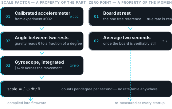 Figure 1 — The previous experiment’s output becomes this one’s instrument. The scale factor needs a known angle, which gravity supplies; the zero point needs nothing but a board at rest.
1. Hardware and Firmware Setup
The rig is unchanged from the previous experiment: an STM32F407G-DISC1 board and a GY-521 breakout carrying an MPU-6050, connected over I²C at 400 kHz, with the sensor’s data-ready line wired to a GPIO. EmbedStudio samples target RAM over SWD while the firmware runs, so every number below came out of a build that does nothing but read raw counts.
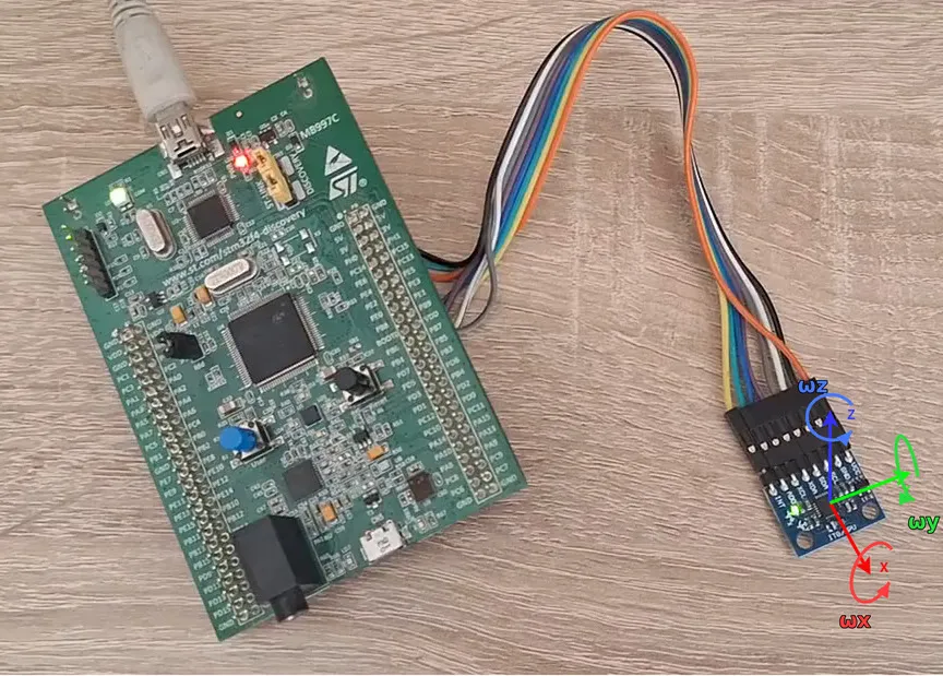 Figure 2 — The same rig as the accelerometer experiment. This time it is the three rotation axes that are being calibrated.
Two things changed in firmware.
The gyroscope full-scale range is now written explicitly. GYRO_CONFIG is
set to 0x00 — ±250 °/s, a nominal 131 LSB/(°/s). That is also the power-on
default, so the register already held the right value. But every gyroscope number
in this article is scaled by it, and a constant that important should be written
rather than inherited. The narrowest range gives the finest resolution, which is
what you want for bias work. As section 4 shows, it is also the range that will
bite you.
The sample rate was checked before anything was integrated. This experiment integrates, and an integral is only as good as its timebase. The check found the read loop running at twice the sensor’s rate. The data-ready interrupt was never being cleared, so the loop ran as fast as the I²C bus allowed instead of waiting for new samples. Worth knowing if you pace a loop off DATA_RDY on this part — the reference firmware carries the fix.
With that corrected, the rate measures 999 Hz on two independent clocks: the host, and the MCU’s own cycle counter. They agree to 0.04 %, and no interval in 961 000 samples went past 1001 µs. The configured 1 kHz is real, and everything below rests on it.
2. What Is Different About Calibrating a Gyroscope
An accelerometer is easy to calibrate because the right answer is known in advance. Whenever the board is still, the only thing it feels is gravity: one g, pointing down, and every axis reads its own share of it. Stand an axis up and it should read exactly +1 g; turn it over and it should read −1 g. That is two known readings per axis, from a table and a steady hand. Two points fix both constants of a straight line: the offset and the slope.
A gyroscope measures angular rate, and nothing in the room rotates at a rate you know. There is no equivalent of standing an axis up. The instrument that supplies a known rate is a rate table, and a rate table is laboratory equipment.
One free reference does survive. At rest the true rate is exactly zero, so whatever the sensor reports while the board sits still is pure error. That fixes the offset, and it costs nothing to repeat as often as you like. It says nothing at all about the slope, because a slope only shows itself when the input is not zero.
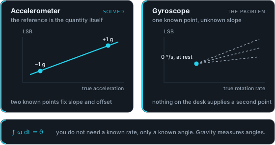 Figure 3 — An accelerometer’s reference is the quantity it measures, so it gets two points. A gyroscope gets one point at zero and no slope, which is the gap the rest of this article closes.
So the gyroscope is short of exactly one thing: a second point, somewhere away from zero. The way to get it is to stop trying to measure rate at all.
∫ ω dt = θIntegrate rate over a movement and what comes out is the angle turned through. An angle you can know without equipment, because gravity marks a fixed direction in the room. Rest the board and the accelerometer reads which way gravity points in the board’s own axes. Move the board, rest it again, and gravity now points somewhere else in those axes — not because gravity moved, but because the board did. The angle between the two readings is the angle the board turned through.
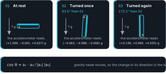 Figure 4 — Three resting orientations from one capture, with what the accelerometer read in each. Gravity never moves, so the change in its direction between two rests is the turn between them. Here that is 93.6° and then 175.5°, measured with nothing but the sensor being calibrated.
That angle is only as good as the accelerometer reporting it, which is why the previous experiment is a prerequisite rather than a citation. A calibrated one pins a resting direction to a fraction of a degree; section 4 shows what an uncalibrated one costs.
So the method writes itself. Rest the board. Turn it. Rest it again. The accelerometer supplies the angle, the gyroscope supplies the integral across the move, and the ratio of the two is the scale factor.
3. The Zero Point, and How Fast It Goes Stale
Power the board up twelve times in a row, warm, without moving it between cycles. Use an inline power switch rather than unplugging, so nothing nudges the board. Average a fixed thirty-second window each time.
The zero point lands somewhere different every time.
| Axis | Turn-on to turn-on spread, LSB | Same, °/s | Heading error after one minute, ° |
|---|---|---|---|
| X | 5.65 | 0.043 | 2.6 |
| Y | 2.33 | 0.018 | 1.1 |
| Z | 1.05 | 0.008 | 0.5 |
Those spreads are quoted to a hundredth of an LSB because the measurement behind them supports it. Within a single cycle the reading wanders by about 5 LSB, but thirty seconds of averaging settles each cycle’s own mean to 0.03 LSB. Even the smallest spread in the table is thirty times that. So the gap between cycles is the zero point actually moving, not the noise of measuring it.
A whole minute of the X axis sitting perfectly still costs 2.6° of heading. An hour of it costs 155°.
And re-zeroing at startup does not end the story. Leave the board running for sixteen minutes at rest, with the die warming by less than one degree, and the zero point walks another 0.026 / 0.020 / 0.008 °/s. That is the same size as the turn-on spread. On the Y axis it is larger.
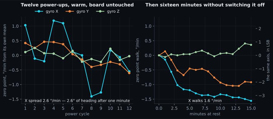 Figure 5 — Twelve power-ups, same board, same temperature, seconds apart — then sixteen minutes left alone. Both panels share one scale, in degrees of heading per minute, so the height of a step is the error it causes: the zero point lands somewhere different every time, and then keeps moving.
So re-zeroing at startup is necessary and not sufficient, which is the two panels of figure 5 side by side. It removes the turn-on component; what is left walks away at a comparable rate. Section 6 puts numbers on both.
One caveat. The session itself warmed by 1.03 °C, so this is not a constant-temperature figure. It is a lower bound on what a device in the field will see. Temperature is recorded in every capture here, but its effect is deliberately not measured. That needs a controlled thermal run, which is a separate experiment.
4. Measuring the Scale Factor Without a Rate Table
Rest the board flat. Tilt it 180° onto its other face. Rest it again.
Gravity points along one axis in the first position and the opposite way in the second. So the angle between the two resting orientations is 180°, and the calibrated accelerometer reads it to a fraction of a degree without being told. Integrate the gyroscope across the move, divide by that angle, and you have the scale factor in LSB per degree per second.
scale [LSB/(°/s)] = ∫ (ω_raw − ω_rest) dt ⁄ θ_from_gravityThat is the whole method. No rate table, no turntable, no jig. It is the same claim the accelerometer experiment made about its six positions, for the same reason.
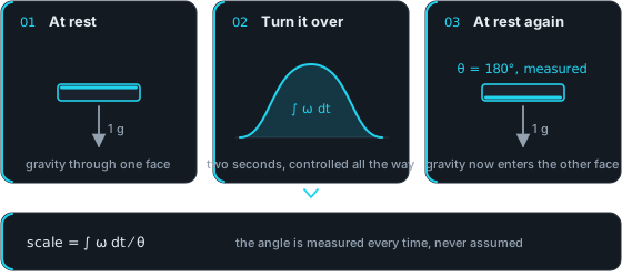 Figure 6 — The accelerometer measures the angle at the two ends. The gyroscope measures the trip between them. Their ratio is the scale factor.
A few practical points before the numbers.
The rest matters more than the movement. The integral runs between two still moments, and the zero point it uses is the average of the two. So the board has to settle properly at both ends. Two to three seconds is enough. The flip itself can be as sloppy as your hand makes it.
The angle does not have to be 180°. It is measured, not assumed. In one capture the tilts ran from 176.4° to 182.5°, and each used its own measured angle. Chasing an exact half-turn gains nothing.
The axis does have to be roughly right. The rotation should be about the
sensor axis you are calibrating. Get it wrong by an angle α and that axis reads
cos α low. The accelerometer will not catch it, because a 180° flip about any
in-plane axis puts gravity exactly anti-parallel whatever α is. The error can be
measured on each tilt and corrected, but the correction assumes one clean
rotation. Smooth flips matter more than accurate ones. Under 2.6° of
misalignment the error is below 0.1 %. At 5° it is 0.38 %. At 10° it is 1.5 %.
Saturation Is Invisible, and It Costs You a Percent
This is the single largest error in the method, and it took two days to find.
At ±250 °/s the sensor rails at 32767 LSB. Flip a board over by hand in less than about a second and a quarter and you go past that. Nothing warns you. There is no status bit, and no kink you would notice on a plot. The reading clips at the peak, the integral loses the area under it, and the scale factor comes out low while looking perfectly healthy.
Pooling the good captures and splitting on whether any sample hit the rail:
| Tilts | Scale factor |
|---|---|
| Unclipped | 132.38 |
| Clipped | 130.49 |
That is a 1.4 % difference, and the more samples a tilt clipped, the lower its scale factor came out. Figure 7 puts one flip of each kind on the same scale. Half the tilts in the first attempts were spoiled this way. The disagreement between captures looked like a real measurement problem for two days.
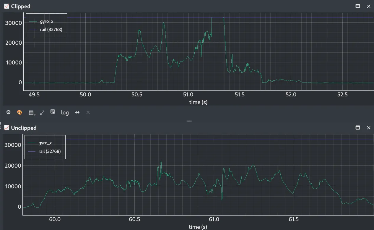 Figure 7 — The same board through nearly the same angle, twice, on the same scale. Top: the flip that clipped, sitting flat on the full-scale rail for 116 milliseconds in the last third of the motion. Bottom: the flip that did not, peaking at two thirds of the rail. The horizontal line is the rail.
The fix is entirely in how you move the board:
- Take two seconds over a 180° flip. For a smooth motion the peak rate is
roughly
(π/2)(180/T): one second gives 283 °/s and clips, 1.2 s gives 236 °/s with no margin, two seconds gives 141 °/s. - Carry the board all the way down. The clipped flips were not the fast ones. They were the ones tipped past balance and left to fall the rest of the way. Clean flips peaked at about twice their average rate; clipped ones at three times, with the spike near the end of the motion. A slow flip with a fast finish clips exactly like a fast one.
- Reject any tilt containing a sample at the rail. It cannot be spotted by eye and it cannot be salvaged.
Switching to ±500 °/s also works. But it changes the constant you are measuring and halves your resolution for the bias work in section 3. Decide that deliberately rather than reaching for it as a fix.
Your Angle Reference Is the Accelerometer, So Its Errors Are Yours
Specifically its offset, and specifically on the axis that reads near zero at the resting positions.
That is the counter-intuitive part. Where an axis reads about 1 g, an offset
shifts both ends of the flip the same way and cancels out. Where an axis reads
about zero, the same offset is a big error on a small number, and it tilts the
apparent direction of gravity by roughly offset / 16384 radians. An offset of
200 LSB is 0.7°, which is 0.8 % of a 90° turn. A 5 % error in that axis’s
scale costs only 0.2 %.
So the sensitive axis changes with the protocol. A 180° flip resting Z up and Z down depends on the accelerometer’s Y offset, and not at all on its Z offset. The fix is to stop at four orientations per revolution instead of two. Then both swing axes rest both ways up, and the capture measures its own reference. It is the previous experiment’s six-position method restricted to one plane, and it costs two extra pauses.
Results
| Axis | Scale factor | vs nominal 131 |
|---|---|---|
| X | 132.2 ± 0.3 | +0.9 % |
| Y | 131.1 ± 0.3 | +0.1 % |
| Z | 130.9 ± 0.3 | −0.05 % |
Only one axis of three deviates. Y and Z sit on the datasheet value to better than 0.1 %; X is 0.9 % above it, confirmed by two independent methods across eight captures. All three are comfortably inside the datasheet’s ±3 % tolerance. That is exactly why the deviation is easy to miss: a part can meet its specification and still cost you 0.9 % of every angle you integrate.
Which axis is off is not predictable. That is the argument for measuring all three rather than trusting one figure for the part.
The ± 0.3 is not the precision of any single measurement. Within one capture, eleven tilts agreed to 0.1 %. Across two different methods and eight captures over two days, the answers spanned 0.39 %. Repeatability is not accuracy, and the second number is the one to quote.
5. Validating It: Does the Integral Track a Known Angle?
A scale factor built from 180° flips has only been tested on 180° flips. The honest test is a longer, continuous rotation, with the truth known at many points along the way.
Roll the board over the same edge again and again so it tumbles across the surface, always the same way, resting briefly on each face. Gravity fixes the orientation at every stop. The gyroscope only has to supply the whole number of turns in between. It can do that even if it clips, because picking the right multiple of 360° needs a few percent of accuracy, not a few tenths.
Over 1438° of turning in 107 seconds, the integrated angle tracked gravity to 0.57° — about 0.04 % of the angle turned.
Gravity’s angle, the integrated rate and the error between them are all calculated variables in EmbedStudio. The whole check runs on the plot, with the board still on the desk.
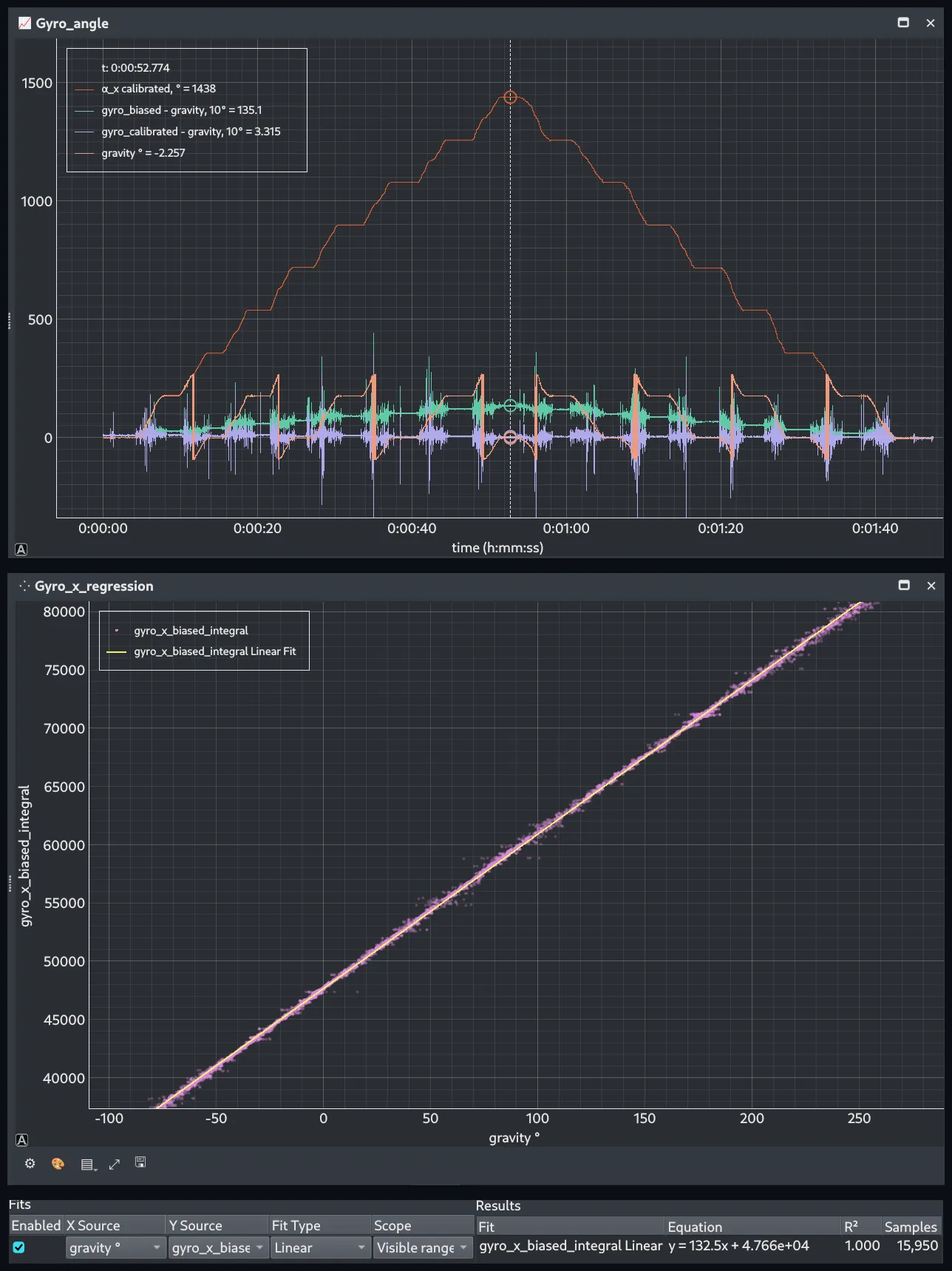 Figure 8 — Top: 1438° out and back. The orange staircase is the calibrated integral, the pale trace below it is the angle gravity reports, and the green and violet traces are the error between them, magnified ten times, with bias correction only and with bias plus scale factor. Bottom: the same integral before any scale factor, plotted against gravity’s angle, with a straight line fitted through it.
The slope of that line is the scale factor. The fit returns 132.5 LSB/(°/s) over 15,950 samples. Section 4’s flips gave 132.2 ± 0.3. Two protocols, one constant. Ignore the R²: it reads 1.000 because a 350° sweep measured against a degree of wobble cannot produce anything else.
Two things about that capture are worth copying.
It turns one way. A scale error multiplies the net angle, so a rotation that comes back to where it started hides it completely. An earlier attempt flipped the board back and forth nine times: 1603° of travel, but a net of only −178.7°. A 0.8 % scale error stayed under 1.4° no matter how many flips were added.
Temperature tracks quality. An earlier run of the same protocol let warm hands take the die from 28 °C to 36.5 °C, and it only managed 2.13°. The run above stayed inside 1.5 °C and reached 0.57°. Keep handling brief.
6. Comparing Compensation Strategies
Here is the line worth taking away from the whole article:
At rest, what ruins your heading is the zero point. While you are turning, what ruins it is the scale factor.
Those are two different regimes with two different constants, and they need two different pictures.
At Rest, for Sixteen Minutes
The board sits untouched, so the true angle is zero and the integral is the error. Four strategies, one capture:
| Strategy | Error at 60 s | Error at 16 min |
|---|---|---|
| No compensation | −204° | −3270° |
| Zero constant measured four days earlier | +4.6° | +55° |
| Two seconds of startup averaging | −0.065° | −19° |
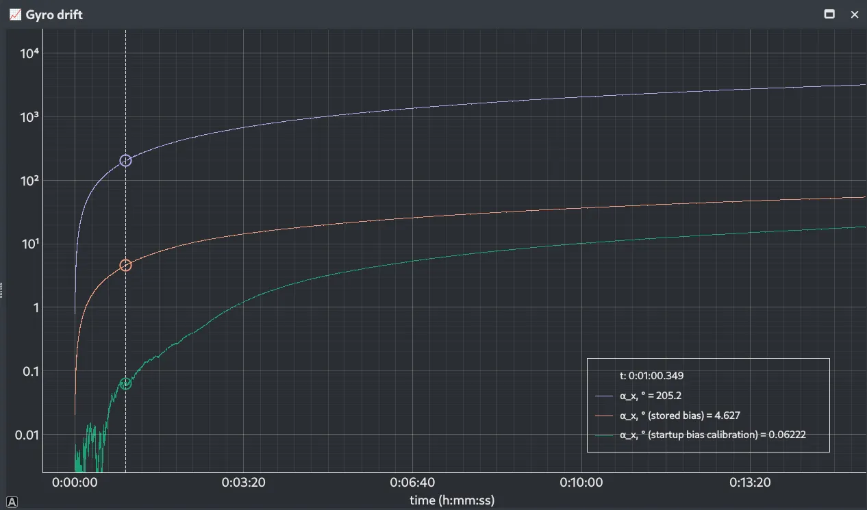 Figure 9 — Sixteen minutes of a stationary board, integrated three ways on a logarithmic axis. The cursor is at one minute: no compensation has drifted 205°, a four-day-old zero constant 4.6°, and two seconds of startup averaging 0.06°.
Startup zeroing beats a stored constant by more than 70× at one minute. Correcting the scale factor here changes almost nothing: over sixteen minutes it moves the error by 0.37° out of 19°. At rest the corrected rate is near zero, so a scale correction has nothing to work on.
While Turning, Through 1438°
Now the same four strategies on the accumulating-rotation capture. The board turns 1438° out and comes all the way back, 2878° of travel in 107 seconds.
| Strategy | Error at the far point (1438°) |
|---|---|
| No compensation | −169° |
| Zero constant measured four days earlier | +11.6° |
| Startup zeroing, board still | +13.6° |
| Startup zeroing + calibrated scale factor | +0.4° |
Fixing the zero point takes 169° down to 13.6°. Fixing the scale factor takes 13.6° down to 0.4°. And that 13.6° is not left-over noise. It is 0.95 % of the angle turned, which is the scale error itself, landing exactly where the arithmetic says it should.
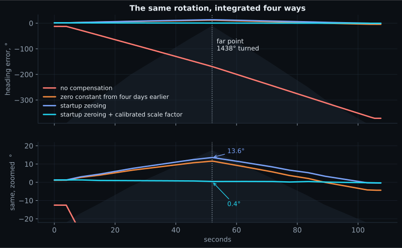 Figure 10 — The same rotation, integrated four ways, with the angle turned shaded behind. The lower panel is the same data zoomed: fixing the zero point leaves 13.6° at the far point, and fixing the scale factor takes that to 0.4°.
Figure 10 holds both regimes in a single trace, because that capture returns to where it started:
- At the far point, correcting the scale factor is worth 13.3°.
- Back at the start, after 2878° of travel, it is worth 0.05°.
The zero-point error does the opposite. It is still there at the end, because the net angle went back to zero but the clock kept running. That is the mirror of the static case, and together they are the rule.
7. Implementing It in Firmware
The model is one line per axis, the same shape as the accelerometer’s:
rate_dps = (raw - bias_lsb) / scale_lsb_per_dps;But the two constants come from opposite places, and that asymmetry is the whole point.
typedef struct {
    float accel_scale[3];  /* LSB/g,       X Y Z — compiled in */
    float accel_bias[3];   /* LSB,         X Y Z — compiled in */
    float gyro_scale[3];   /* LSB/(deg/s), X Y Z — compiled in */
    float gyro_bias[3];    /* LSB,         X Y Z — measured at every startup */
} MPU6050_Calibration_t;
Compile the scale factor in. It is a property of the part. It reproduced to better than 0.1 % within a session and 0.39 % across two days, and it is not going to surprise you.
Do not compile the zero point in. The reference firmware leaves
gyro_bias[] at zero on purpose. Until the startup measurement lands, the rate
output shows the raw offset instead of hiding it behind a stale number.
Average Two Seconds — But Only Once the Board Is Still
How long to average is a trade-off with a measured answer. Take the sixteen-minute capture from section 3 and work out the startup constant from its first half second, its first second, its first two seconds and so on. Then compare each against the constant a settled five-second average picks. One LSB of error carries 0.46° of heading per minute, so every row converts straight into degrees:
| Averaging window | Constant lands off by | After 1 min | After 10 min | After 1 hour |
|---|---|---|---|---|
| 0.5 s | 1.19 LSB | 0.5° | 5.4° | 33° |
| 1 s | 0.78 LSB | 0.4° | 3.6° | 21° |
| 2 s | 0.11 LSB | 0.05° | 0.5° | 2.9° |
| 5 s | reference | — | — | — |
| 10 s | 0.17 LSB | 0.08° | 0.8° | 4.8° |
Half a second is not enough averaging. The noise it leaves on the constant is worth half a degree in the first minute and a third of a turn in an hour. Two seconds gets within a tenth of an LSB of the settled value. Ten seconds is further out than two, not closer: by then the zero point itself has moved, so the longer window is averaging over something that is no longer constant. Nothing past about five seconds is worth waiting for. Two seconds.
The gate in front of it is not a nicety. A zero point is only meaningful if the part is decoupled from everything that moves it, and a hand is not a decoupling. In one capture the board was still being held at power-on, and a plain two-second average came out 0.79 °/s wrong. That is eighteen times the movement the zeroing exists to remove, and enough on its own to put that run 24° out over a minute.
The gate does not make the constant more accurate. It stops the firmware committing to one until the board is still.
“Still” has to become three numbers the firmware can compare. Every 0.2 s it measures the block just finished and requires all three of these at once:
s_ω = √( var ωx + var ωy + var ωz )   ≤  30 LSB     (about 0.23 °/s)
s_a = sd( |a| )                       ≤  0.005 g
e_a = | mean(|a|) − 1 g | ≤ 0.05 gs_ω, how much the rate wobbles inside the block, catches rotation. A board on a table measures 8 to 9 LSB; one being held measures 40 and up. The threshold sits at 30, between the two.s_a, how much the gravity reading wobbles, catches vibration and knocks. It also catches what the gyroscope is blind to: a board slid or carried at a constant attitude is moving without rotating at all. A resting board tops out at 0.0023 g.e_a, how far gravity is from 1 g on average, catches steady acceleration. A lift, or a vehicle pulling away, shifts the mean without making either of the first two wobble. Its tolerance is wide because it also has to absorb the accelerometer’s own offset drift, which was 16 mg on the Z axis over four days.
The other half of the gate is what happens to a block once it is judged:
block passes  →  n += 200 samples
block fails   →  n  = 0           everything banked so far is thrown away
n ≥ 2000      →  bias = mean of the banked samples, and the gate closes
Stillness is judged on short blocks, not on the window as a whole. One bad block discards everything saved so far, so the constant always comes from a stretch that was still the whole way through. The window starts the moment the board settles and is abandoned the moment it stops being still.
The first version tested a fixed, non-overlapping two-second window instead — and on a real flip-and-rest capture it never zeroed at all. The longest continuous still stretch there was 2.58 s, and only two stretches reached two seconds at all. A fixed window has to land almost exactly on one of them by luck. Checking in blocks costs one counter and no buffer.
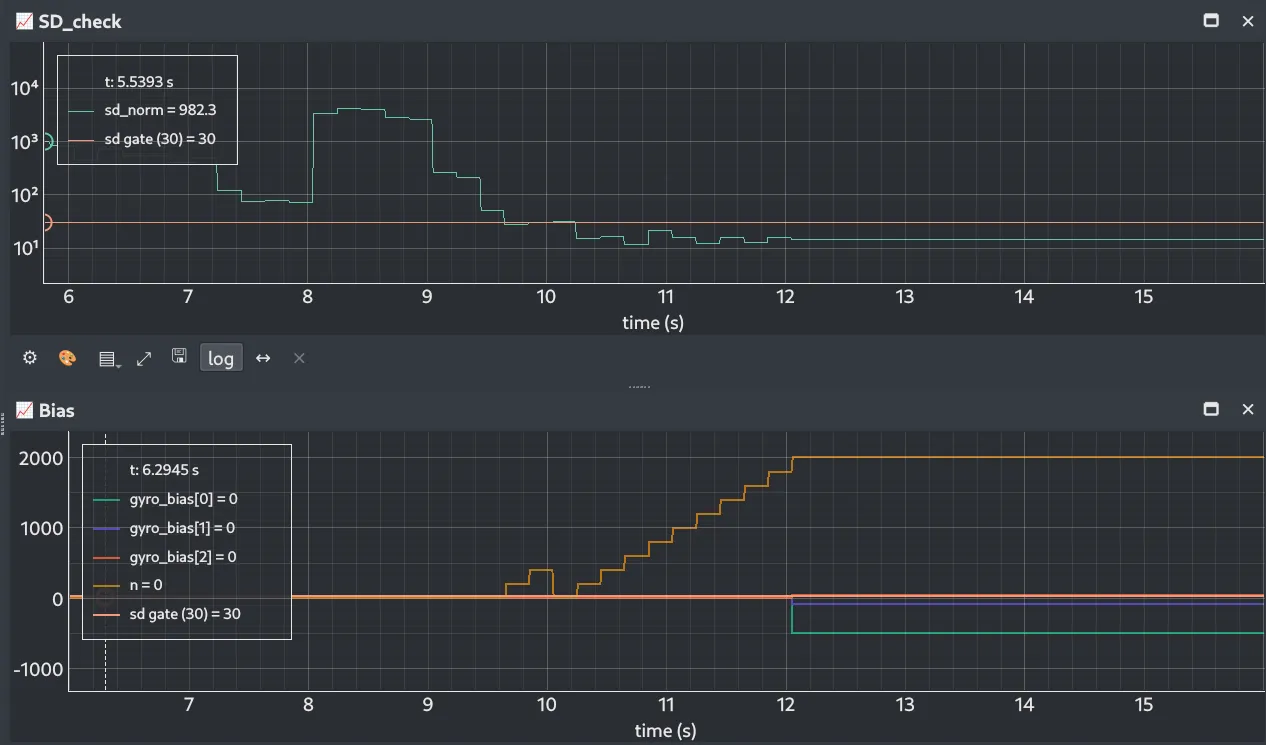 Figure 11 — The gate deciding, on a logarithmic axis. Top: how much the rate wobbles, against the threshold of 30. Held in the hand it runs a hundred times above the line; set down, it settles well below. Bottom: samples banked. Two blocks are banked and thrown away at ten seconds, then the count climbs in 200-sample steps to 2000, and the three zero constants step off zero together two seconds later.
On target it behaves exactly as intended. Power-cycled while held in the hand, the gate refused for 15.2 seconds and threw away three partial windows. Two seconds after the board was set down, it accepted. The block it accepted wobbled by 9.9 LSB. While the board was being held the same measure typically read 602, and peaked past 20000. That is not a close call for a threshold of 30.
One Honest Limitation
The gate proves the board has stopped moving. It cannot tell whether the board has stopped warming, and one just out of a warm hand has not. After the zero was taken in that capture, the X zero point walked 14.5 LSB — 0.11 °/s — in the next fourteen seconds. A board that had been sitting managed 3.4 LSB over sixteen minutes.
Clamping the board under a weight cut the mechanical noise fourfold and left that walk untouched, so it is not the board creeping. Whether it is temperature these captures cannot prove, because time and temperature move together in all of them.
So zero after the board has been sitting, not the moment you put it down.
8. The Numbers, in One Place
What belongs to the part. The sensor runs at 999 Hz, measured on two clocks that agree to 0.04 %. Its three scale factors came out at 132.2, 131.1 and 130.9 LSB/(°/s) for X, Y and Z. One axis is 0.9 % above the datasheet’s 131 and the other two are inside 0.1 % of it, all three well within the ±3 % allowed. Those numbers are compiled into the firmware, and they should stay put.
What belongs to the moment. The zero point landed somewhere different after each of twelve warm power-ups, spread over 0.043 °/s on the worst axis. Left running, it then walked about as far again over sixteen minutes. One LSB of error in it costs 0.46° of heading a minute, and that is what fixes the startup average at two seconds. Those two seconds have to be still ones: taken while the board was held, the same average lands 0.79 °/s out.
What the two together buy. Turned through 1438° in 52 seconds with both constants applied, the integrated heading finished 0.4° from the truth. The same rotation with no compensation at all finishes 169° out. Checked against gravity at every resting position along the way, the integral tracked to 0.57° rms — 0.04 % of the angle turned.
9. What This Experiment Showed
- A gyroscope’s zero point is a property of the moment, not of the part. It moved 0.043 °/s between power-ups on a warm, untouched board, and kept walking at a comparable rate afterwards. Measure it at every startup.
- The scale factor is a property of the part, and you can measure it with gravity and a pair of hands. Tilt between two resting positions, let the accelerometer read the angle, integrate the rate across the move, divide.
- Only one axis of three deviated. X was 0.9 % out; Y and Z were within 0.1 %. All three sat inside the datasheet’s ±3 %. Which one is off is not predictable, so measure all three.
- Bias error grows with time; scale error grows with angle. At rest for sixteen minutes, correcting the scale factor was worth less than half a degree. Turning through 1438°, it was worth 13.3°.
- The gyroscope’s own full-scale limit destroys the measurement that calibrates it. A 180° hand flip in under 1.2 s saturates, the integral loses area, and the scale factor reads low with no visible symptom.
- A zero point is only as good as whatever the board rests on. The part has to be decoupled from everything that moves it, and careful hands are not enough. A two-second average taken while the board was held landed 0.79 °/s out, eighteen times the drift it was meant to remove. Put the board down, and let the firmware decide when it is still.
The series rule now reads the same from both sensors:
Scale is a property of the part. Bias is a property of the moment.
Every number above came out of firmware that read raw counts and nothing else. The integration, the four-way comparison and the scale-factor arithmetic all ran in EmbedStudio against live data. That made it cheap to be wrong several times before being right. The saturation problem in section 4 was found by re-running the same capture through a changed processing chain, with no rebuild and no re-flash. Only then did the constants move into firmware.
References
- InvenSense, MPU-6000 and MPU-6050 Product Specification, Rev. 3.4 (PS-MPU-6000A-00, 2013) — PDF. Source of the nominal 131 LSB/(°/s) at ±250 °/s that the measured scale factors are compared against in section 4, and of the ±3 % sensitivity tolerance.
- InvenSense, MPU-6000 and MPU-6050 Register Map and Descriptions, Rev. 4.2
(RM-MPU-6000A-00, 2013) —
PDF.
Source of the
GYRO_CONFIGandSMPLRT_DIVvalues behind the ±250 °/s range and the 1 kHz sample rate in section 1.
Next Experiment
Experiment #004: How Long Is One Sample, Really?
Every number above is an integral, and an integral is a rate multiplied by a time. The rate is calibrated now. The time was assumed — one millisecond per sample, because that is what the sample rate register was set to, and nobody measured it.
The next experiment measures it, inside the MCU, on the sensor’s own data-ready line. The first reading is not 1000 µs, and the reason is one field in one register. A timing error of that size lands on an integrated angle exactly as a scale factor error does, which makes it the cheapest correction in the series.
After that, the two sensors go together. The gyroscope is right in the short run and drifts; the accelerometer knows which way is down at every instant and never drifts, but says nothing about heading and is contaminated by any movement of the board. Combining them into one orientation that holds at both ends of the timescale needs a rate, a direction, and a trustworthy interval between updates.
Frequently Asked Questions
How do you calibrate a gyroscope without a turntable?
You do not need a known rate, you need a known angle, because integrating rate gives angle. Rest the board, tilt it onto another face, rest it again. A calibrated accelerometer reads the angle between the two resting orientations from gravity alone, and the gyroscope integral across the move divided by that angle is the scale factor. On the module measured here this reached better than 0.1% repeatability within one capture, hand-held, with no fixture of any kind.
Why does a gyroscope need re-zeroing at every startup?
The zero point is not a property of the part, it is a property of the moment. On the module measured here it landed somewhere different after every power-up, spread over 0.043 °/s even with the board warm and untouched between cycles. That is 2.6° of heading error after one minute of sitting perfectly still. Averaging two seconds of output at startup and subtracting it beat a constant compiled in from an earlier session by a factor of 71 after sixty seconds.
Is the gyroscope scale factor worth calibrating?
On this part one axis of three was 0.9% above the datasheet's 131 LSB per °/s while the other two sat within 0.1% of it, and all three were inside the datasheet's ±3% tolerance. Which axis deviates is not predictable, so all three have to be measured. A 0.9% gain error is 0.85° on a 90° turn, and unlike a zero-point error it grows with the angle turned rather than with time.
What is the difference between gyroscope bias and scale factor error?
Bias error accumulates with time and scale error accumulates with angle. At rest for sixteen minutes an uncompensated gyroscope drifted 3270° here, essentially all of it bias, and correcting the scale factor changed that by less than half a degree. While turning through 1438° in under a minute, fixing the zero point left 13.6° of error and every bit of it was scale factor. Those are the two regimes and they need different constants.
Can an MPU6050 saturate during hand calibration?
Yes, and it is the single largest error in this method. At ±250 °/s the sensor rails at 32767 LSB, and flipping a board over by hand in less than about a second and a quarter goes past that. The reading clips, the integral loses the area under the clipped peak, and the scale factor comes out low with no visible symptom. Take two seconds over a 180° flip and carry the board all the way down, because a slow flip with a fast finish clips exactly like a fast one.
Should gyroscope calibration constants be stored in firmware?
The scale factor yes, the zero point no. The scale factor reproduced to better than 0.1% within a session and 0.39% across two different methods and eight captures over two days, so compiling it in costs nothing. The zero point moved every power-up and kept moving afterwards, so a stored value describes the device as it was rather than as it is. This is the same split the accelerometer showed in the previous experiment, reached from the other direction.
Source Code
The firmware and supporting files for this experiment are available here:
View experiment repository