
MPU-6050 Bring-up on STM32
Connecting an MPU-6050 IMU to an STM32 microcontroller and verifying I2C communication.
Published
Every embedded project starts with a simple but important step: making the hardware work.
Before implementing sensor fusion algorithms, motion tracking, or advanced control systems, the first challenge is establishing reliable communication between the microcontroller and external devices.
In the first EmbedStudio experiment, we connect an MPU-6050 inertial measurement unit (IMU) to an STM32 microcontroller and verify communication over the I²C bus.
This experiment establishes the foundation for future work with sensor data acquisition, visualization, and real-time embedded debugging.
Experiment Goal
The goal of this experiment is simple:
- Connect the MPU-6050 sensor to an STM32 microcontroller.
- Configure the I²C interface.
- Detect the sensor.
- Read identification registers.
- Confirm that communication is working correctly.
At this stage, we are not yet processing motion data. The focus is establishing a reliable hardware and firmware foundation.
Hardware Setup
The experiment uses:
- STM32 development board
- MPU-6050 IMU module installed on GY-521 board
- ST-Link debugger/programmer
- I²C interface
The MPU-6050 combines:
- 3-axis accelerometer
- 3-axis gyroscope
- I²C communication interface
This makes it a popular sensor for robotics, drones, balancing systems, and motion tracking applications.
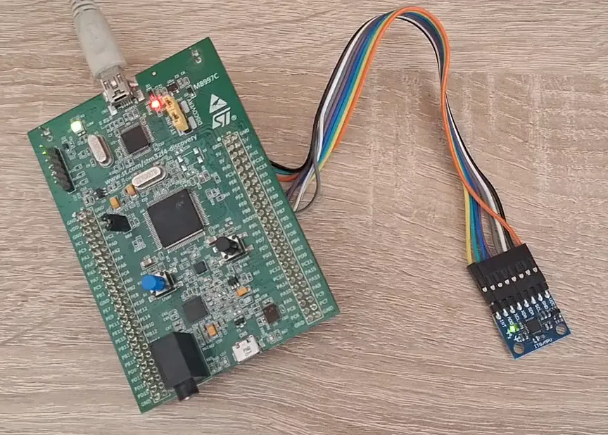
STM32 connected to the MPU-6050 module.
Wiring
The MPU-6050 communicates with the STM32 through the I²C interface.
The connection is:
| GY-521 | STM32F4Discovery | Note |
|---|---|---|
| VCC | 5V | Onboard LDO provides 3.3 V for IMU |
| GND | GND | Shared ground, kept short |
| SCL | PB6 (I2C1_SCL) | 4.7 kΩ pull-up to 3V3 |
| SDA | PB9 (I2C1_SDA) | 4.7 kΩ pull-up to 3V3 |
| AD0 | GND | Selects address 0x68 |
| INT | PB8 (EXTI8) | Data ready interrupt |
The I²C address of the sensor depends on the state of the AD0 pin. With the default configuration, the device is usually detected at address: 0x68
Firmware Bring-up
The firmware performs the following steps:
- Initialize the STM32 clock system.
- Configure the I²C peripheral.
- Scan the I²C bus.
- Detect the MPU-6050 device.
- Read the sensor identification register.
The first communication test is intentionally simple.
A successful response confirms:
- correct wiring,
- correct voltage levels,
- correct I²C configuration,
- functional sensor hardware.
Verification
During hardware bring-up, debugging tools are extremely valuable.
A logic analyzer can be used to verify:
- START and STOP conditions,
- device addressing,
- acknowledge responses,
- register transactions.
Proving the bus
Before touching the register map, confirm that something is acknowledging on the bus. A scan across the 7-bit address space is the fastest sanity check:
for (uint8_t addr = 1; addr < 128; addr++) {
    if (HAL_I2C_IsDeviceReady(&hi2c1, addr << 1, 2, 10) == HAL_OK) {
        printf("ACK from 0x%02X\r\n", addr);
    }
}
A healthy board answers at 0x68. If nothing answers at all, the fault is almost always one of three things: SDA/SCL swapped, no pull-ups, or the I2C peripheral clock never enabled.
WHO_AM_I
With an address in hand, read register 0x75. The MPU6050 returns 0x68 —conveniently the same as its address, which has confused a lot of people.
uint8_t who = 0;
HAL_I2C_Mem_Read(&hi2c1, 0x68 << 1, 0x75, 1, &who, 1, 100);
// who == 0x68
A returned 0x98 or 0x72 means the part is an MPU6500 or MPU9250 clone.
The register maps overlap enough to bring up, but not enough to trust blindly.
Waking the device
Out of reset the MPU6050 sits in sleep mode with the SLEEP bit of PWR_MGMT_1 (0x6B) set. Until it is cleared, every measurement register reads back as zero — which looks exactly like a wiring fault and costs a surprising amount of debugging time.
uint8_t wake = 0x00;
HAL_I2C_Mem_Write(&hi2c1, 0x68 << 1, 0x6B, 1, &wake, 1, 100);
While in that register, it is worth selecting the gyroscope’s X-axis PLL as the clock source (0x01) instead of the internal 8 MHz oscillator. It is measurably more stable over temperature and costs one byte.
First Motion Data
After confirming communication with the MPU-6050, the next step was to verify that the sensor measurements correspond to real physical movement.
The accelerometer outputs raw measurements along three axes:
- X-axis
- Y-axis
- Z-axis
The board was slowly tilted by hand while monitoring the values in real time.
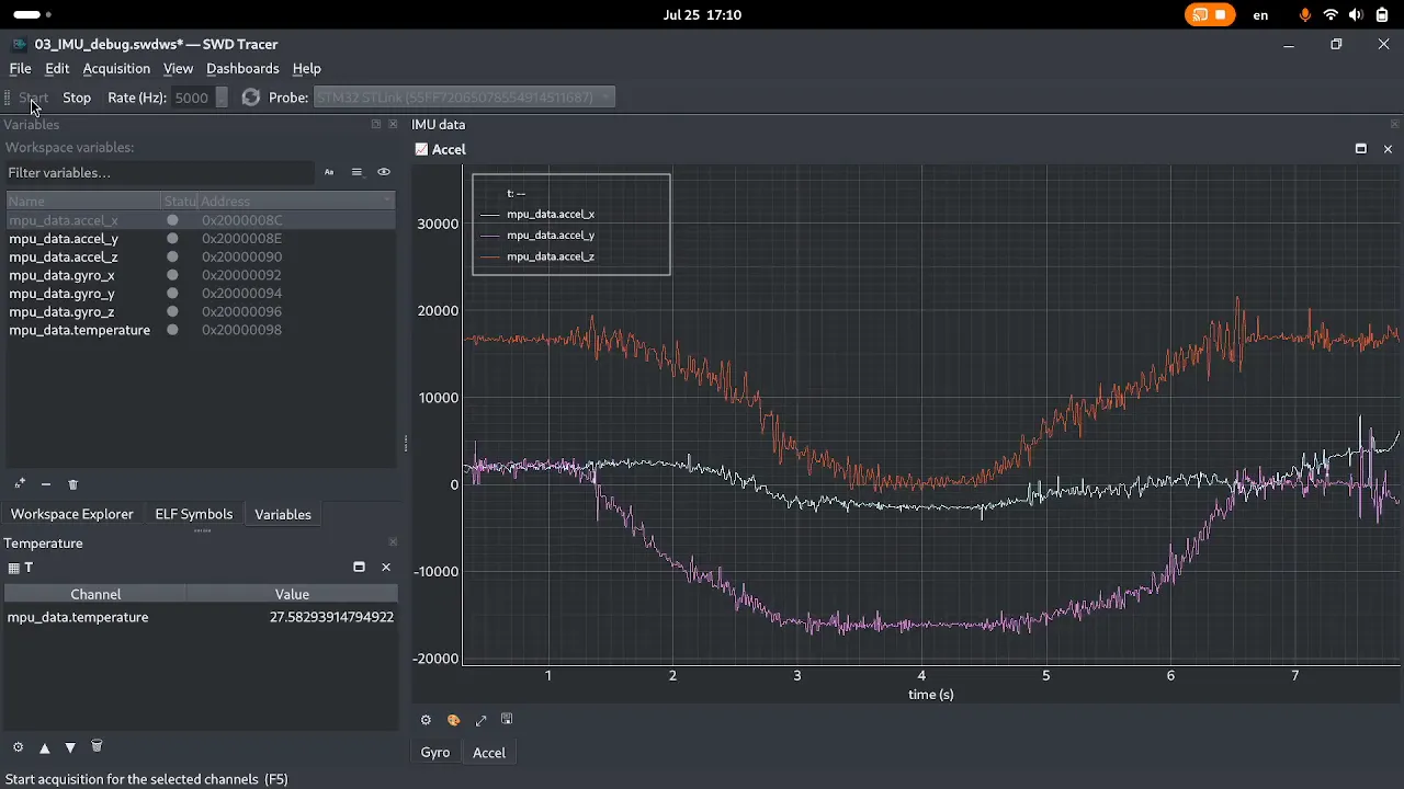
Raw accelerometer measurements while changing the sensor orientation.
Several observations can be made from the captured data:
- The Z-axis remains close to ±1g depending on the sensor orientation, because gravity is the dominant acceleration component at rest.
- Tilting the board causes the gravity vector to move between the X, Y, and Z axes.
- Sudden movements introduce short acceleration spikes.
- The three axes together provide enough information to estimate the orientation of the sensor.
At this stage, the data is still raw and unfiltered. Further experiments will focus on calibration, filtering, and converting these measurements into meaningful orientation information.
This type of visualization is especially useful during early hardware bring-up because it allows firmware behavior to be verified without relying only on logs or manually inspecting memory values.
Why Start With Bring-up?
Many embedded development problems are not caused by complex algorithms.
They usually come from small integration issues:
- incorrect wiring,
- wrong peripheral configuration,
- incorrect device address,
- timing problems,
- unexpected hardware behavior.
A structured bring-up process reduces uncertainty and creates a stable platform for further development.
Debugging the Invisible State
The most challenging part of embedded development is often not writing the code — it is understanding what is happening inside a running system.
During this bring-up process, several questions naturally appear:
- Was the I²C initialization executed correctly?
- Did the sensor respond with the expected values?
- Are configuration registers set as intended?
- Are measurements changing when the device moves?
At this stage, the firmware is simple enough that serial prints and a debugger are usually sufficient. However, as applications grow more complex, observing internal state becomes increasingly difficult.
Real-time systems introduce additional constraints: adding logging changes timing, breakpoints stop execution, and manually inspecting variables provides only a limited view of system behavior.
Tools that provide visibility into firmware execution without significantly disturbing the running application become increasingly valuable as the complexity of the system grows.
The following experiments will explore different approaches to observing embedded systems, from raw sensor acquisition to real-time visualization.
Results
The first experiment successfully achieved:
✅ STM32 and MPU-6050 hardware connection
✅ I²C communication established
✅ Sensor detected by the microcontroller
✅ Foundation created for further sensor experiments
What’s Next?
The next experiments will build on this foundation:
- Reading accelerometer values
- Reading gyroscope values
- Sensor calibration
- Converting raw data into physical units
- Real-time visualization
- Sensor fusion and orientation estimation
The journey from raw sensor registers to meaningful motion information begins here.
Follow the Experiment Series
This article is part of the MPU-6050 Journey series.
Upcoming experiments:
- Experiment #002 — Reading Accelerometer Data
- Experiment #003 — Reading Gyroscope Data
- Experiment #004 — Sensor Calibration
- Experiment #005 — Orientation Estimation
Follow along as we explore embedded development, debugging techniques, and system observability while building practical STM32-based projects.
Source Code
The firmware and supporting files for this experiment are available here:
View experiment repository